

How To Clean Dash Circuit Board To Bulb Contact Points
The Arduino Uno lath has over twenty pins that you tin can use for many different applications. In this post I'll give you a complete and applied overview of the main Arduino Uno pins.
If y'all're starting with Arduino, or if you're already a software programmer and desire to learn more well-nigh the bridge between software and hardware on an Arduino board, then you've come to the right place!
In this mail you'll see :
- What are the pins you tin use
- What you can do with them
- And some tips on how to connect other devices to your Arduino pins
I'll also give yous some examples of sensors/actuators that yous tin can use with each pin functionality.
This mail service is focused on Arduino Uno board, merely near of the explanations (except for the pivot numbers on the circuit board) are also valid for whatever other Arduino board.
>> Lookout this video equally an boosted resource to this article:
Y'all are learning how to use Arduino to build your ain projects?
Check out Arduino For Beginners and learn pace by step.
Afterward watching the video, subscribe to the Robotics Dorsum-Terminate Youtube channel so y'all don't miss the next tutorials!
Arduino Uno pin diagram
Here'southward a global visual description of all the pins you tin find on an Arduino Uno board.
You may find that quite difficult to empathise at first. So, permit's pause down each kind of pin, one by 1.
Ground pins
If there is 1 thing, and simply one thing that yous should remember with the ground, information technology's: always connect all grounds of your circuits together, and make sure all components are correctly linked to the basis. Basis pins are oftentimes represented past GND on schematics.
The ground is essential for the Arduino board to measure and fix any voltage. Basically a voltage is a departure of potential between two points: here you accept the basis and another betoken.
So, if everything in your excursion is connected to the same basis, all the voltages can be compared and their value is relevant. If you don't have a mutual ground, and then what does 3.3V mean ? Is is greater than a 5V value you measured from some other signal of your circuit ?
It'due south like measuring the top difference between 2 persons: if i of them is continuing on a box, then the ground reference is not the same. And you can't get a valuable measurement if yous don't place the 2 persons on the same level.
Well, I won't go into more details, only y'all run into the point.
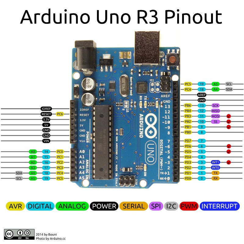
Arduino Power pins
Power goes ii ways:
- Y'all take to ability your Arduino Uno board from an external source
- You tin also power some components plugged to your board
Powering the Arduino Uno board
For powering the Arduino Uno lath, you have different options. The beginning ane is simply to connect your Arduino board to your computer using a USB cable – ordinarily yous get one when you lot social club an Arduino board.
You can too apply the DC power jack to ability your Arduino board with 7-12V. If you lot are using some hobby servomotors powered by your Arduino, y'all might desire to use the DC power jack. The ability coming from the USB cable is lower. It's great for communication between your board and your computer (or other Arduino boards), simply might exist not enough to power some real motors.
So, you've already got 2 ways to power your Arduino Uno board. At present, if you look at the power pins on the circuit, you lot'll run across a Vin pivot.
Y'all tin utilize this pin to provide 7-12V to your board. Very applied when you demand to utilize an external power source and connect information technology directly to your board. And, as you tin can guess, if you use the Vin, you also need to use the ground correctly, past connecting it to the ground of the external power source.
Note that the USB and DC power jack already accept the ground integrated and which connects to anything you plug on them. In fact, the metal part that you tin touch around the USB connector is directly linked to the footing!
Powering components from the Arduino Uno power pins
As you can guess, whenever you lot connect an external component to your Arduino Uno board, you demand to connect it outset to the footing.
So you tin use several dissimilar pins to power it on. Among them are the three.3V and 5V power pins.
Note – this is important – that the Arduino Uno is operating under 5V. So, for every output pin that nosotros'll meet in the following of this post, be sure to think that. If you lot plug a 3.3V component to a 5V power source, you might damage the component.
At that place are two alternatives to that: use the three.3V ability source from the Arduino (integrated voltage bridge), or use 5V with a voltage level shifter. You lot can easily connect a three.3V to a 5V component, provided that you transform the voltage betwixt them, using resistors or directly a level shifter component.
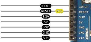
Arduino Digital pins
You can detect xiv digital pins on an Arduino Uno lath. They are easily recognizable, from 0 to 13 on the circuit board.
Reading/Writing on digital pins
Yous'll utilize digital pins to read data from some components (sensors) and write data to other components (actuators).
A digital pin tin have simply 2 states: LOW or HIGH. You tin can consider them every bit binary pins.
Low ways that the voltage on the pin is 0V. HIGH ways Vcc, which is 5V hither for Arduino Uno.
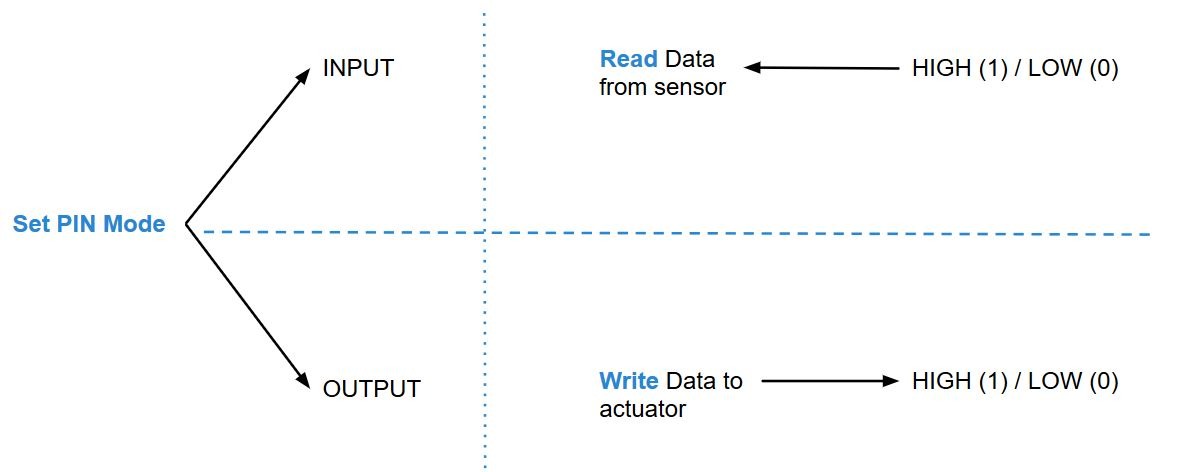
Earlier y'all tin can actually use a digital pin, you demand to configure its style. A digital pivot tin can either exist on INPUT more or OUTPUT mode. When in INPUT fashion, you'll employ information technology to read data. When in OUTPUT mode, you'll use it to write data.
Later on you've set a mode for the pin – usually in the setup() office of your Arduino program with pinMode() – you'll be able to read/write the state of the pivot with digitalRead()/digitalWrite().
If you have fix the pin to INPUT mode, and then you can read its land, which will be either High or Low.
When reading, any voltage practical to the pin lower than 0.8V will be considered as LOW, and whatever voltage greater than 2V will be considered as High. Thus, I stress again that you should correctly connect all the grounds in your circuit together, or else the Arduino Uno won't exist able to read a valuable information! If y'all don't get reliable and stable data, always first check about the basis, it's very likely that the problem is coming from there.
For examples of how to utilize digital pins to control a component, check out this Arduino LED tutorial.
For how to use digital pins to read data from a sensor, cheque out this Arduino button button tutorial.
And if yous desire to go to a more avant-garde level with digital pins, check out how to make digitalWrite() faster.
PWM
Some of the digital pins can be used to write a PWM.
A PWM (Pulse Width Modulation) is basically a fashion to get a specific voltage (ex: four.1V) with only Loftier/Low (5V/0V) states. The PWM creates a pulse running at a given frequency – 500Hz for Arduino Uno. Then, a duty wheel parameter will tell what percentage of each pulse is in the HIGH state or Low state.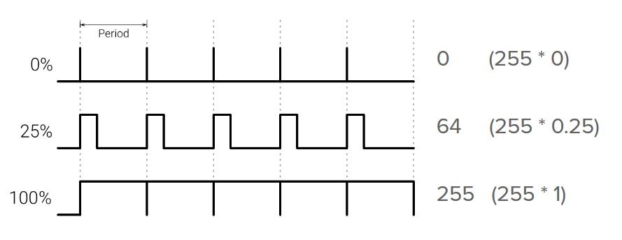
The frequent change of HIGH/Depression states produces an average voltage output. For example, at a fifty% duty cycle (50% of the fourth dimension HIGH, fifty% of the time Low), the output voltage would exist ii.5V.
Of grade, this explanation is really simplified, merely that's all you demand to know to go started with the Arduino PWM.
Now, you can use the PWM only on some digital pins, which have a "~" side by side to their number. The Arduino Uno pins compatible with PWM are the pins three, five, 6, 9, 10 and 11. And so yous have 6 pins where you can create a PWM, using the analogWrite() function.
This tin can be quite useful to control some actuators that require a fine voltage tuning, and are non only switched on or off.
If we take the example of a LED, you tin can use the analogWrite() function to change the brightness of the LED.
Interrupt pins
And… There is another available functionality for the digital pins! You tin use some of them as interrupt pins in your Arduino programme.
For Arduino Uno, the choice for those pins is quite limited. Only digital pins 2 and 3 can be used as interrupt pins.
And then, how is it working ?
When you create an Arduino plan, yous have to know that your code is running line by line, with no possible multithreading.
Let'due south say you connect a push button to an interrupt pin (and to the ground!). In your Arduino program, y'all can attach a specific office to be triggered whenever you press the push. So, instead of having to continuously read the push state, you tin can directly use the interrupt behavior to launch your part. Call back of it equally a push notification, just like on your phone. Information technology tells you when there is new content, or a specific action to do. Acquire how to use Arduino Interrupts in your code.
However, this doesn't mean that you take solved the multithreading event. When the execution of the program switches to your role called by an interrupt, it will also terminate the execution of the current program and come back to it only subsequently the interrupt office has finished.
If yous want to learn more than nigh how to multitask with Arduino, check out this consummate tutorial on this subject.
Arduino Analog pins
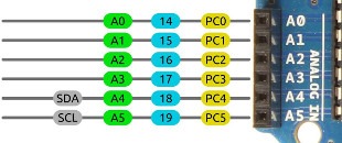
You can find 6 analog pins on an Arduino Uno board. Y'all'll detect them nigh the power pins, and they're easily recognizable, from A0 to A5.
Read a value from an analog pin
An analog pin is useful to read values that can't exist just 0 or ane. Let's say you have a potentiometer and want to get the percentage of the potentiometer value. With a digital pivot you lot could know when the potentiometer is at minimum and maximum position, but naught else. With analog pins, yous have all the values in between.
Notation that the analog functionality on those pins is simply for reading. Usually they are even called "Analog input pins". Yous can't write an analog value through those pins, don't forget that!
So, how is an analog input pin working ?
Starting time, information technology will receive an input voltage and read this voltage. Permit'due south say the pivot reads 2.5V. Then, an ADC (Analog Digital Converter) volition change that analog value into something your Arduino programme can understand – a digital value.
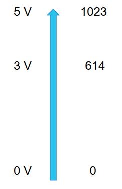
The Arduino Uno lath has a x $.25 ADC. The resolution can be different if you employ other Arduino boards. So, what does ten $.25 mean ? But that the resolution is 2^10 = 1024. Thus, the value you go when y'all read data from an analog input pivot is between 0 and 1024.
Coming back to our 2.5V example: 2.5V is 50% of 5V (Vcc). In your Arduino program, you will and so get the value 512. From this value, you tin can easily reverse the computation and get the information about the voltage that was applied.
Also – and it tin can be quite confusing at showtime – remember that the analogWrite() function for PWM is only available for some of the digital pins, and non for analog pins at all.
Using an analog pin as a digital pin
Even if y'all can merely read from an analog pivot, yous can also cull to use it as a "simple" digital pin. (simply the opposite is non true)
If the pivot can read any value between 0 and 5V, then information technology will be able to read just values beneath 0.8V (Depression) and values above 2V (Loftier).
To use an analog pin as a digital pin, you lot but have to set the fashion for the pin, equally yous would practice for digital pins in the setup() function of your Arduino program. And then, you can use the digitalWrite() and digitalRead() functions and it will work perfectly.
Communication protocols through Arduino pins
Here is where things start to get interesting. Communication protocols over Arduino Uno pins volition allow you to use more advanced sensors and actuators. Yous'll create more than complex and useful applications.
There are iii main communication protocols you can use with an Arduino Uno lath, through the pins of the circuit: UART, I2C, and SPI.
But… Nothing is displayed on the circuit!
Don't panic, the communication protocols are using the existing pins on the excursion.
In fact, most of the pins are configurable to use alternate functions, sometimes upward to 4 alternate functions for just ane pin. Only let's continue things simple hither.
Pins for UART – Serial
UART is the most used protocol for Arduino – at least when you brainstorm.
When you connect your Arduino Uno board to your computer, and communicate via the Series library, well… You are using UART!
Y'all tin can besides notice the two required pins for UART directly on the Arduino Uno board, on pins 0 and 1: RX and TX. R stands for "reception" and T for "transmission". This is a bidirectional advice.
![]()
Note that the Series used past USB is the same equally the i used with pins 0 and 1. And so, if y'all want to connect another device to the RX/TX pins of your board, remember not to employ the Serial through USB.
In another Arduino boards, like Mega, in that location are several different available UARTs. But for Arduino Uno, you lot simply have one.
If however, you want to use more UARTs, you tin can always practise that with the SoftwareSerial library. This library allows you to utilize any other digital pins for UART purpose. Although there is a large departure here: "true" Series uses hardware functionality of the Arduino Uno lath, which is very fast and doesn't consume much computation ability. The SoftwareSerial is the opposite: it compensates for hardware with computation ability. And so, start with the standard hardware UART beginning, and and so you'll see if you need more serial ports for your application (in this instance I recommend you switch to an Arduino Mega to get many hardware UARTs).
To connect a component to the Arduino Uno pins and utilize Serial communication, you'll need four cables:
- Ane betwixt the RX of the component and the TX of the Arduino
- 1 between the TX of the component and the RX of the Arduino
- If the component is not powered externally, one cable to ability it from the power pins of the Arduino
- And… I for connecting the ground
If you're interested in communicating between a Raspberry Pi board and an Arduino lath via Serial, check out this Raspberry Pi Arduino Serial tutorial.
Pins for I2C
I2C is a charabanc protocol, with a multi-main/multi-slave architecture. But to keep things unproblematic – and most of your applications volition just need that – let'south only talk virtually the one-master/multi-slave role of the architecture.
Basically, imagine a bus of data where all the information goes through. The head of the motorcoach is the master. Now, you can add any new component to the bus, configured as a slave. Besides, each component has its own ID.
The master device will ship information and requests to a slave device, by communication on the bus and providing the ID of the slave. If the master needs a response, the slave will ship dorsum the response to the motorbus. In one case the master has received a response, it tin can send the next instruction/request.
Usually, you'll utilize your Arduino Uno board every bit the principal, and yous'll connect one or several components (usually sensors) to the I2C bus, with each a different ID. On the software side, you'll use the open source Arduino Wire library.
But, to which Arduino Uno pins should yous connect all those components ?
For I2C you can't come across any indication directly on the circuit board.
![]()
You'll demand 4 cables to use an I2C omnibus:
- One to connect the SCL pivot (clock)
- Another one for the SDA pivot (information)
- 1 to ability on the components on the passenger vehicle
- And one to brand the common ground
Some examples of I2C compatible components:
- MPL3115A2 temperature sensor
- MPU6050 gyroscope + accelerometer sensor
- TCS34725 color sensor
Pins for SPI
SPI is some other protocol based on a primary-slaves architecture.
Y'all can use information technology to connect your Arduino board to multiple devices. Note that the communication speed is faster than for I2C and UART, just it's not suitable for mid-long distance advice (more a few centimeters for the cable). Every bit for the other communication protocols, y'all can directly use the open source SPI library on your Arduino programs.
When you're using an SPI device and want to connect it to some pins on your Arduino board, here are the pins you need to utilize:
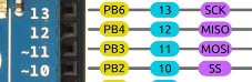
The cablevision arrangement for connecting devices with SPI pins is a little bit more complex. You need 6 cables minimum:
- SCK pin (clock)
- MISO pin (Primary In, Slave Out)
- MOSI pin (Primary Out, Slave In)
- One for each CS/SS (Bit Select/Slave Select). For each additional slave, you'll need to add one more connection to an Arduino pin.
- One for powering the components
- And one for the common footing
Some examples of SPI compatible devices:
- AS5047D magnetic position sensor
- MAX31855 thermocouple-to-digital sensor
Get started with Arduino Uno pins
As you lot saw in this postal service, you have a huge number of options when it comes to using Arduino Uno pins.
If you lot just begin with Arduino, try first to utilise the digital and analog basic functionalities.
So, you lot tin can outset to go farther with interrupts, PWM outputs, etc.
And finally, there'due south an infinite number of sensors/actuators y'all can connect to your Arduino Uno board to create your side by side project!
You can also connect several Arduino boards together, or even a Raspberry Pi board.
Well, now that you accept a meliorate agreement of Arduino Uno pins, time to get your hands dirty!
If you lot don't have an thought of what to do with all those pins, check out the different devices I introduced every bit examples in this post, this might exist a good way to start and go more ideas.

Source: https://roboticsbackend.com/arduino-uno-pins-a-complete-practical-guide/
Posted by: phillipsnursucher.blogspot.com
0 Response to "How To Clean Dash Circuit Board To Bulb Contact Points"
Post a Comment